TSC logo

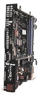
Model 210MV Features and Specifications


FEATURES

  • Compatibility with all TYPE 170 and TYPE 179 Controllers
  • RS232 Serial Communications Capability
  • DIP Switch selection of Enhanced Monitoring Functions
  • Systems Communications through Controller Unit as an option
  • Microprocessor based design
  • RMS voltage monitoring (not peak-voltage-only)
  • Self-diagnostics
  • Internal monitor Hardware and Software Watch Dog
  • Real Time Clock
  • Event Logging of records retained through power failure
  • Enhanced Monitoring including Red Monitoring
  • Simple command/routine enables all functions for automatic testing while retaining desired set-up for intersection
  • Displaying permissive programming on Personal/Laptop Computer


BENEFITS


SPECIFICATIONS

SIZE In accordance with Type 170 Specifications
POWER REQUIREMENTS 89 to 135 volts ac, or as per applicable specification.
60 +/- 3 Hertz 1 Amp SLO-BLO fusing
TEMPERATURE -34°C to +74°C Operating       -50°C to +85°C Storage
CHANNELS MONITORED 16 Channels, 18 optional - add "-18" to model number.
MONITORED SIGNALS +24 Volt dc
Controller Watch Dog, 1.0 seconds or 1.5 seconds. 48 ac field wire voltages (both polarities of sinusoid and out-of-phase voltages are monitored). 54 as an option, ("-18")
DISPLAYED INFO All active channels, power, and FAULTS on LEDs.
RESET `RESET' button prevents defeating unit operation
BASIC FUNCTIONS Conflicting Green or Yellow on any two or more non-compatible channels (full or half-wave). FAULT signal status retained through power failure in EEPROM and displayed on LED indicators.
ENHANCED FUNCTIONS Minimum Yellow Timing, Sequence and Multiple Output monitoring selectable for each channel. Absence of Red selectable for each channel. Selections made using DIP switches. Low (Brownout) and high AC line voltage. Internal monitor Hardware and Software Watch Dog. Failure due to removal of program card.

Meets CALTRANS TYPE 170 requirements. Performs RMS (not peak) and out of phase voltage monitoring for Green, Yellow and Red inputs. Supplied with Model 210-DC Diode program card for programming permissives and Yellow inhibit. Uses internal Menu-driven Set-up Program and DIP switches for making monitoring selections by channel. Example of Event Log print-out below.
SITE  FFFF 00FF  DATE 12/16/94  TIME 18:26:32
LAST SETUP CHANGE 12/16/94 18:13
LAST TIME/DATE CHANGE 12/10/94 08:34
EVENT LOG OVERFLOW 08/22/94 08:36
LAST PRINT OUT 12/16/94 10:07
CLEARED EVENTS 12/16/94 10:08
# DATE TIME 1111111 EVENT
1234567890123456
001 08/22/94 08:33 GGGGRRRRYYYYGGRR TRANS FAIL 4G 4R
002 07/15/94 23:20 CONTROLLER RESET
003 07/15/94 23:19 POWER UP
004 07/15/94 20:23 RRRRYYYYGGGYYRRR POWER FAIL
005 06/05/94 12:18 YYYYGGRRGGRRRRRR WATCH DOG FAIL


Home Page


Monitors · Tester · Flashers · Load Switches · LMS · COMMS · Harnesses · SSR · Isolators · Ped. Signal

Contact TSC for further information